Hoffman Consultants are experts in the design and assembly of metal stud framing. We use current software to create complete, easy-to-read metal stud shop drawing sets — including plans, elevations, sections, and 3D isometric drawings so field crews can build with confidence.
We design your cold-formed project using your preferred clip manufacturer, including The Steel Network, ClarkDietrich, Simpson Strong-Tie, or others.
For a quote on metal stud shop drawings, email architectural and structural drawings plus the 5400 specification to quotes@hoffmanconsultants.com.
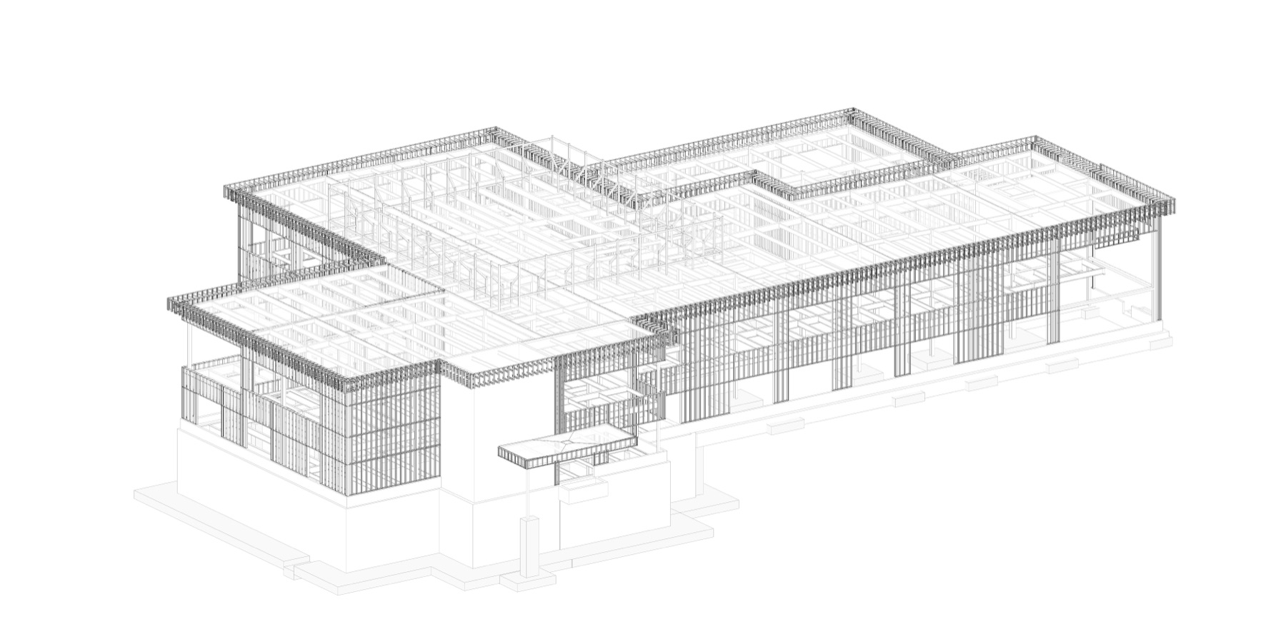
What you receive
- Engineered cold-formed metal framing shop drawings
- Plans, elevations, sections, and 3D assembly isometrics
- Calculations prepared under a Professional Engineer when required
- Clips and connections detailed to your specified manufacturer
- Optional BIM coordination — see our BIM page
Sample shop drawing sets
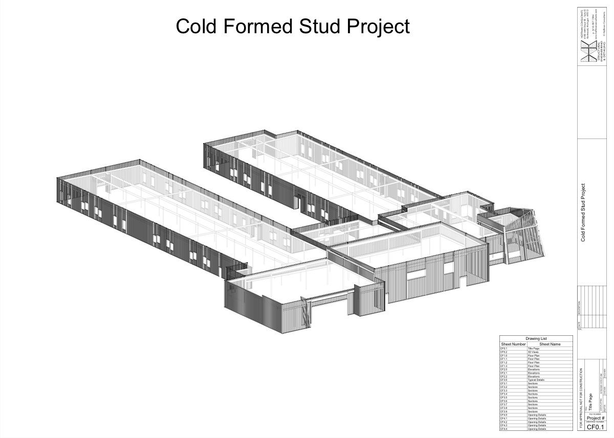
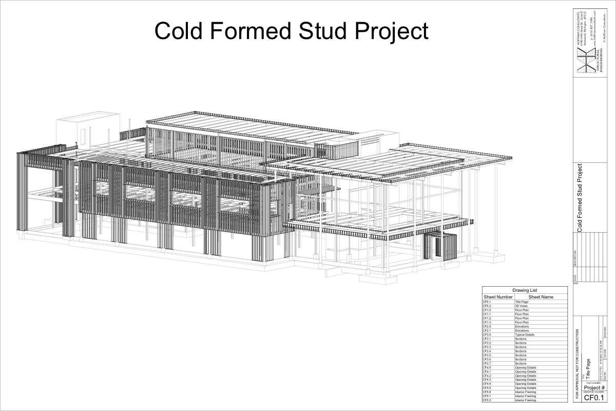
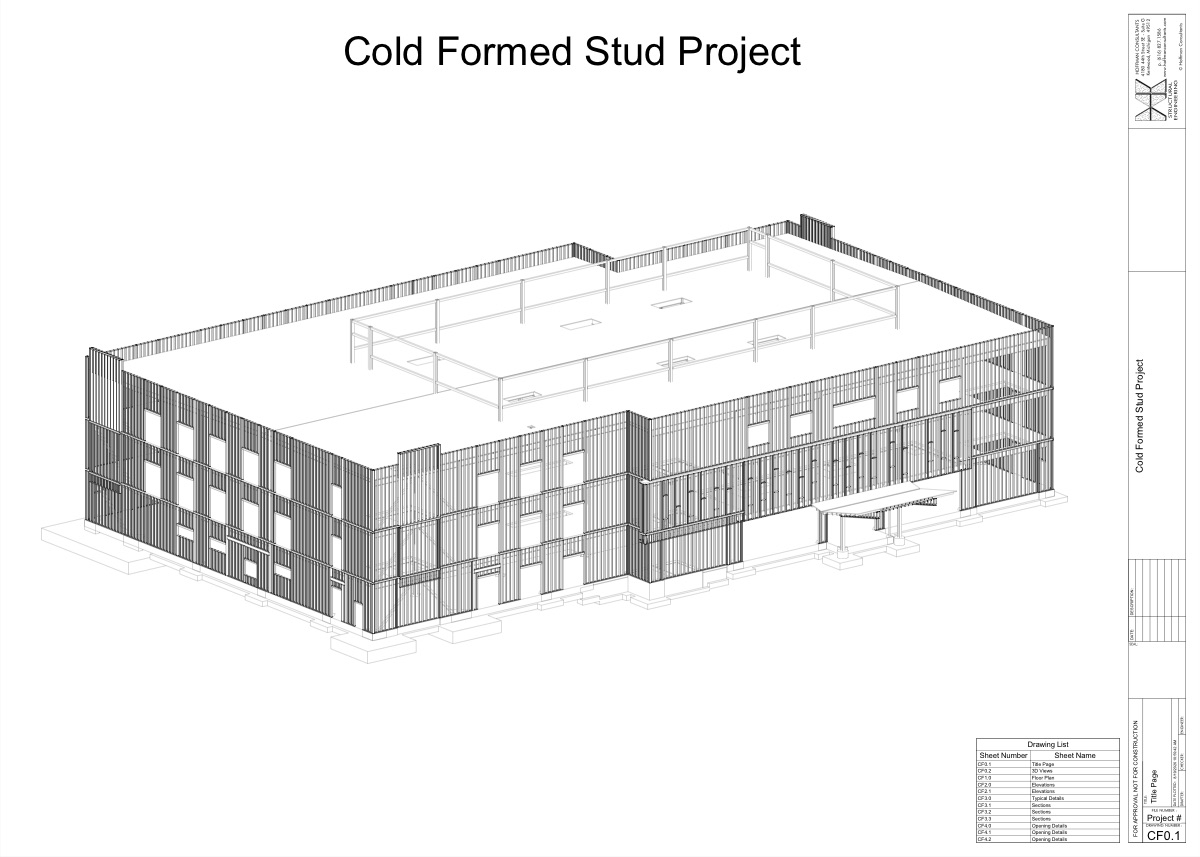
Recent CFMF packages — title sheets and drawing indexes. Open the PDF for the full set.
Metal stud framing FAQ
Answers contractors look up
- Why is it required to have engineered shop drawings?
- Are drawings required for all studs?
- What is a deflection clip?
- Will lighter studs always save money?
- Do I always need a supplemental clip for each connection?
- How much deflection space is enough?
- Is bridging required in all walls?
- How are stud sizes called out or designated?
- Is it important to follow the shop drawings in construction?
- Do wood studs and metal studs behave the same during construction?
- The specs require PE-stamped shop drawings and calculations. How do we get started?
- What is the use of metal stud shop drawings if they are not required in the specification?
- Are special inspections required for metal studs?
Why is it required to have engineered shop drawings?
In most cases the engineer of record only checks the main stud required. This is based on the height, wind speed and exposure, and the type of material being supported. The supply-side engineer at Hoffman Consultants uses that information to specify fasteners, assemblies, and layout of studs for the entire project.
The unsupported length is typically the distance between the floor and the next story or roof — commonly 8 to 14 feet. Minimum required wind velocity for most buildings is 115 MPH ultimate (90 MPH nominal), except at coastlines. Exposure factors increase load on open sites; Exposure “C” commonly results in about 25–30 PSF on components and cladding.
Design first checks strength (shape, gage, and steel grade must resist loads without yielding), then serviceability — how much bending (deflection) cladding can tolerate. Brick veneer often requires L/600. For a 12-foot span that is only about ¼ inch. Unlike wood studs, cold-formed metal studs come in many sizes and gages; gage also affects fastener capacity. Shop drawings detail how studs assemble and anchor to the structure, including headers, sills, and multi-ply jambs at openings.
Are drawings required for all studs?
Generally only exterior walls, bearing walls, and combinations of both are required to be designed and shown on shop drawings. Interior non-bearing studs are not subject to significant lateral loads and usually support flexible wallboard. Interior studs are often thin (20, 22, or 25 gage) while exterior studs are usually a minimum of 18 gage.
What is a deflection clip?
A deflection clip slides or slips in the vertical direction. It only supports the stud horizontally. Unless a stud is designed for vertical load, incidental bearing can buckle it. Slip connections guard against that — for example when a spandrel beam deflects under floor load and would otherwise dump load into the studs below.
Will lighter studs always save money?
Lighter studs save money most of the time, but not always. Sometimes fastener counts increase and labor cost rises enough to offset material savings.
Do I always need a supplemental clip for each connection?
A regular stud nested in a track generally will not require a base clip if the track matches the stud gage — the flanges still need anchoring and the track must be anchored to the floor. Unless it is a bearing wall, the top connection usually requires a slip-type connection. Base clips are generally required at the bottom of built-up jamb members at doors and windows.
How much deflection space is enough?
Assuming dead load is already applied when the wall is built, a safe maximum deflection is often the floor span in inches divided by 360. Example: at 30 feet, 12 × 30 / 360 = 1 inch.
Is bridging required in all walls?
If both sides of a wall are sheathed, members are considered braced against buckling in the weak axis and additional bridging is often not required. For non-bearing walls, additional bracing is usually not specified. On bearing walls Hoffman Consultants typically specifies bridging at 4 to 6 feet on center vertically to protect the wall during construction before sheathing is installed.
How are stud sizes called out or designated?
Hoffman Consultants utilizes SSMA standards. Example: 600S162-43 — 600 = 6 inch depth, S = stud, 162 = 1.62 inch flange, 43 = 0.043 inch nominal thickness. Example track: 362T125-54. Gage and mils are also used (1 mil = 0.001 inch). Common conversions: 25 ga ≈ 18 mils; 22 ga ≈ 27; 20 ga drywall ≈ 30; 20 ga structural ≈ 33; 18 ga ≈ 43; 16 ga ≈ 54; 14 ga ≈ 68; 12 ga ≈ 98 mils.
Is it important to follow the shop drawings in construction?
Once shop drawings are approved they become the contract drawings for construction. Assemblies and fasteners must be followed or a redesign is required. Hoffman Consultants works with customers to configure assemblies for field efficiency — which may not match construction drawings exactly.
Do wood studs and metal studs behave the same during construction?
Dimensions can look similar, but assembly behavior is different. Metal studs are relatively flexible without sheathing bracing. Wood has inherent stiffness as a solid section. Deflection and weak-axis buckling are critical for cold-formed steel; bridging, bracing, and web stiffeners over bearing points are often required. Professionally prepared shop drawings detail each assembly to meet design requirements.
The specs require PE-stamped shop drawings and calculations. How do we get started?
Hoffman Consultants provides professionally prepared cold-formed metal stud shop drawings and calculations — plans, elevations, and 3D isometrics of assemblies. We work fixed-fee or hourly. For a quotation, email PDF architectural and structural drawings plus the project specifications (including the 5400 specification) to quotes@hoffmanconsultants.com.
What is the use of metal stud shop drawings if they are not required in the specification?
Benefits include: clear framing assemblies; avoiding over-anchoring; easier field checking; 3D assembly references; jambs and headers designed for wind; cut sheets for bearing walls; optional bill of material (added fee); and early identification of field problems before installation.
Are special inspections required for metal studs?
Special inspections are not required unless dictated by the owner, architect, engineer, building authority, or general contractor. Hoffman Consultants recommends a special inspector familiar with cold-formed trades to verify proper installation — starting from clear shop drawings under a qualified design professional.
Get a quote
Send your drawings
Architectural + structural PDFs and the 5400 specification.
Start quote email